
We have been building and tuning racing engines for a long time now. We know what it takes to make a good engine. The cylinder head is the secret.
We have been tuning the Honda B-Series engine for years. We have been getting very good results, but there is always room for improvement. We have come to a point whereby in order to extract more power, we need a better head design. At 130+ bhp per litre, we start running into problems with pre-detonation due to combustion chamber design.
We examined the heads very closely and decided not to touch the ports as we have seen 145 bhp per litre, without the need for porting running on leaded race fuel.
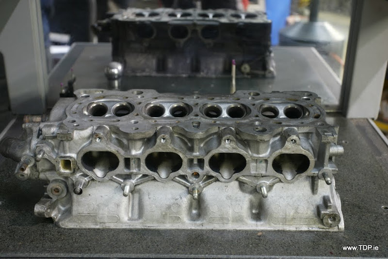
The ports are over-sized for the standard capacity of the engine, resulting in the loss of mid range torque. No power is to be found here without extensive port filling and reshaping. The combustion chamber is actually a very bad design compared to the rest of the cylinder head. It has very shrouded valves and the chamber volumes are all different shapes and volumes. We also noticed that the sharp edges would not help with high compression and 95 octane fuel. We decided that from our experience with other race engines that remodelling of the combustion chamber would be the best solution. This will allow for higher compression ratios without the problem of pre detonation running pump 95-ron fuel.
The below photo shows clearly the shrouded valves and sharp unfinished edges which are not good for flow at low valve lifts and may cause detonation under high load conditions.

So, we decided to scan the head and machine the chambers. Over the years we have gained very valuable test data form our combustion chamber remodelling process.
The first part of the process is to scan/digitize the head. For this we have a dedicated Renishaw Cyclone Series 2 machine.

Then, we place a stripped B16 head on the machine.
The first part of the process is to set up the scanning stylus for capturing the 2D facets. We will use that later to construct the body of the head in Solidworks 3D solid modelling software.
In this photo you can see the square ended parallel 3mm probe.


In the below image you can see the probe being calibrated on a 50mm reference sphere.

The next 3 photos show how we set the Z-plane normal to the head face. 3 points are taken and the machine uses a plane through these 3 points as the flat of the head face. This is particularly useful if the part dose not sit flat on the machine table. Not a problem in this case, but we always measure.


In the next 2 images, you can see the machine measuring the 2 main dowel holes on the head. This is done to align the head in the X & Y plane. The machine measures the 2 bores and calculates their centre position and aligns the X-axis along the line.


One of the last set-up steps is to find the centre of datum bore and call it the origin or X0,Y0. This is done by measuring the bore and calculating the centroid (this allows finding the centre of elliptical holes also). The datum is then set at X0.000,Y0.000. The last operation is to check the Z and set it at Z0.000. Now the machine has a local datum on the part at X0.000,Y0.000,Z0.000


Now the scanning begins with allowing the machine to measure all the bolt & dowel hole for reference purposes. At this time we also measure the the outside profile of the head and combustion chamber shallow recesses.
The below images will show this.


Now that we have an accurate 2D drawing of the head in plan view. e turn our machine to 3D. This require the use of a round ruby ball stylus.

Again the stylus is calibrated on the reference sphere.

We then scan the head along the Y-axis. This allows us to capture the chamber shape and the angles and contours involved.


We repeat the above process for the X-axis.


Then we import all the scanned data to Solidworks. Over a number of hours we are able to replicate the head and make some improvements to the design. We also use finite analysis software to improve the deign. Here is what it look like on the CAD screen:

The the 3D Solid CAD data is sent to our CAM (Computer Aided Machining) package for processing and creating of tool paths for the machining centre. Once created and simulated in the CAM package we now have a program to drive the DMU 70 eVo machining centre. This is what the tool paths look like on screen:

This program is sent to the machine and run. First with a 1 mm offset. Its very clear from the below images that the original head chamber are very inconsistent in shape and volume.


The program is then run at an offset of 0.1mm. This time the chambers look more even but are still not perfect.

Now the finishing pass is run.


The head is now surfaced in the same set-up. This ensures the best possible accuracy for volume in all chambers.
Some images to show the finished head:


A quick reminder of how it used to look.
